The ATS-909 / DX-398 is certainly one of the great portable shortwave receivers ever made. It performs reliably, has many fine features, and is widely available at a reasonable cost. Countless people use it as a source for news, information, and entertainment around the world. The radio performs better than many full-sized tabletop receivers of years past. It well outperforms my old DX-160, and does more than my Heathkit HR-1680. Despite this, there is room for improvement.
I will not repeat the numerous improvements to the ATS-909 that may be found on other modification websites, such as davemoison.org but will limit my comments to a few changes that mean the most in my shortwave listening experience with the receiver. I first obtained this dandy radio in 1995, and have taken a soldering iron to it numerous times. It is not a difficult radio to work on, but one must be careful with its surface-mount components. There are a few cables and delicate connectors that should be handled with care. Considering those factors, I suggest making changes described below.
- Anti-Chuffing
- Beep Removal
- Finer SSB tuning (makes steps smaller, but you lose some ability to tune between 1 kHz increments); parallel SVR5 with a 4.7k resistor for 10 Hz steps
- Replace ceramic filter CF6 with a narrower one for better adjacent channel rejection on FM
- Restore segments of FM tuning range (diode change enables TV audio in the USA and some assisted listening devices).D310 on tuner board.
- Short resistor R7 to ground - allows gain reduction to zero
- AGC mods as described here; IF clipping mod not necessary
- Audio bandwidth enhancement
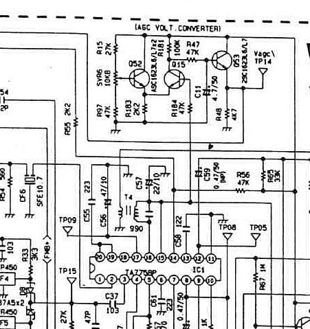
Improved AGC response:
- Popular modification sites on the web have suggested reducing capacitor C57 (on Pin15 of IC1) to a value of 10 uF. I disagree, and have had better results leaving it at 22 uF.
- Capacitor C11 should be verified to be 4.7 uF.
- The radio does not exercise enough control over strong signals. Local amateur and utility signals frequently slam the S meter to full scale and distort badly. I have solved the problem by increasing R181 to 470K. This slows the rate at which C11 recharges and also allows a more effective control of IF circuit gain.
ATS-909 / DX-398 AGC Schematic:
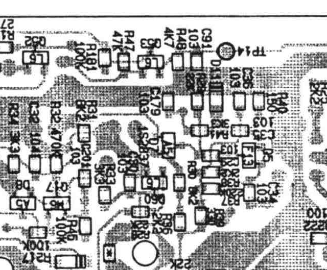
ATS-909 / DX-398 AGC Parts Layout:
Audio Modifications for Better Bass Response:
To achieve a low end rolloff around 15Hz,
coupling
capacitors should be increased as
indicated:
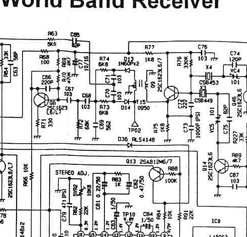
- C67 and C68 (output from product detector) 4.7uF
- C80 (AM / SSB audio into IC3)
- C93 and C94 (input to audio amplifier IC6)15uF@10v
- C106 and C107
(input to the L and R power amplifiers IC4 and IC5)10uF@10v - C116 and C117
(output of L and R power amplifiers IC4 and IC5)1000uF@10v - C132 and C133
(output of auduo amplifier IC6) 10uF@10v
Product Detector Schematic
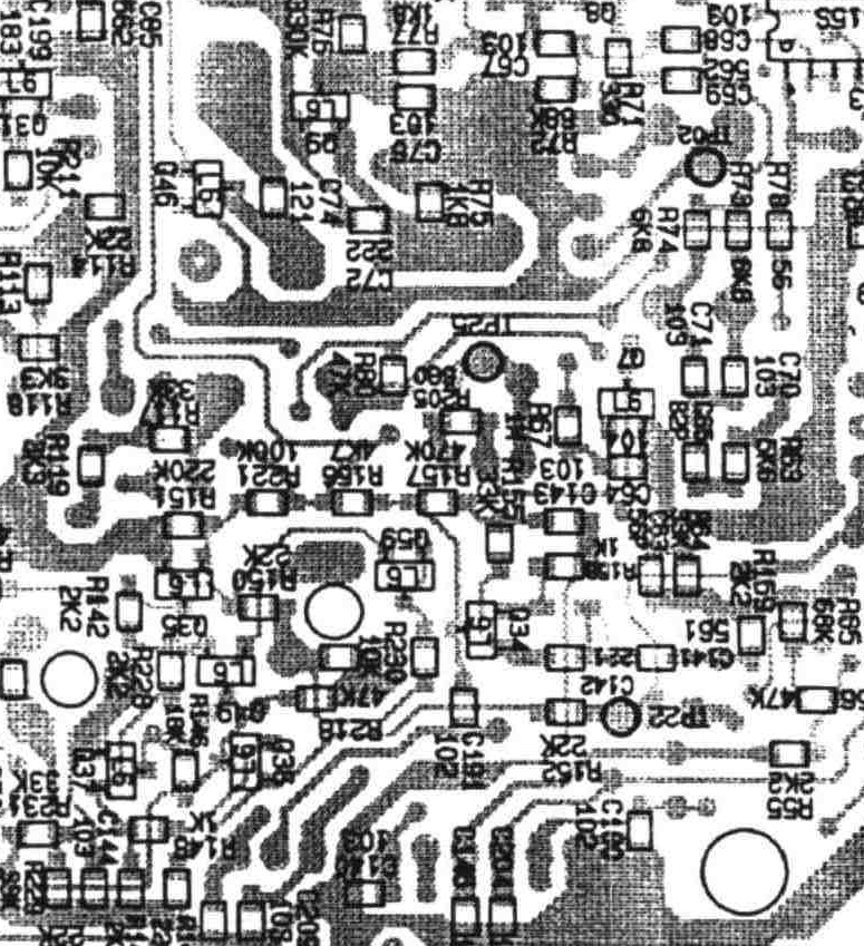
Product Detector Layout
For better oscillator frequency alignment without a counter, connect the audio to your computer sound card and follow this ATS-909 / DX-398 alignment procedure and refer to the ATS-909 / DX-398 circuit board images and alignment pectrograms..
© 2005 - 2026 AB9IL.net, All Rights Reserved.
Written and curated by Philip Collier / AB9IL.
About Philip Collier / AB9IL, Commentaries and Op-Eds, Contact, Privacy Policy and Disclosures, XML Sitemap.