Why NASA Created the Apollo Unified S Band System
Signal Characteristics
Unified S Band System Normal Operating Modes
Unified S Band System Backup and Emergency Modes
Unified S Band System Ranging Measurements
Unified S Band System FM and Video Signals
Non - Unified S Band System Signals
Interception of Apollo Spacecraft Signals
Further Reading on Apollo Spacecraft Communications
See the Video Series about Apollo S Band Communications
Why NASA Created the Apollo Unified S Band System
Launch, in-space operation, and re-entry, of any spacecraft require tightly coordinated actions on the ground and on the spacecraft. Information must be passed both ways, and use radio links to accomplish it all. Voice communications connect the people involved: covering the moment to moment status of the flight, experiences and decision making that are part of manned spaceflight. Data communications carry data from spacecraft elctrical, guidance, life support, and other systems back to earth, while comand and control data are sent to the spacecraft for the purpose of updating spacecraft systems with essential data, configuring the spacecraft apropriately for its phase of flight, and accomplishing various tasks that are impractical or unsafe for astronauts to attempt. Note that the communications infrastructure evolved from what was used for aircraft flight testing into a whole new and much more complex system to support missions in low earth orbit, and then extended range missions to the moon.
The Mercury and Gemini programs, used a growing kludge of radio systems on VHF and UHF for voice and telemetry. Tracking was accomplished by use of a C band transponder, similar in function to a basic aircraft mode A transponder, which was interrogated by a ground based radar. There were too many different radios, cables, antennas, power supplies, and other equipment in the old system for trips to the moon. Reliability, range, and bandwidth had to be increased; weight, power consumption, and size had to be reduced. Apollo also would include something entirely new in the space program: live television from the astronauts. Therefore, the new space telecommunications system needed to be highly innovative to meet the needs of the ambitious Apollo program.
It was decided that the new Unified S Band System, built by the Collins Radio Company, would incorporate multiple signals onto one uplink from the ground and one downlink per spacecraft. The technnology grew out of the coherent doppler and the pseudo-random range tracking system which was being developed by the Jet Propulsion Laboratory. Subcarriers for voice and telemetry were added to the tracking signal in a manner that would allow each to function without interference from the others. It was an elegant and very capable solution for the communications challenges posed by manned flight to lunar distances. At any time during a mission, one tracking station in view of the spacecraft, with one high gain antenna could provide tracking, command, and communications services. Using the huge parabolic antennas of the Deep Space Network and smaller antennas of the Apollo / Manned Space Flight Network, constant high quality contact would be maintained with Apollo spacecraft.
|
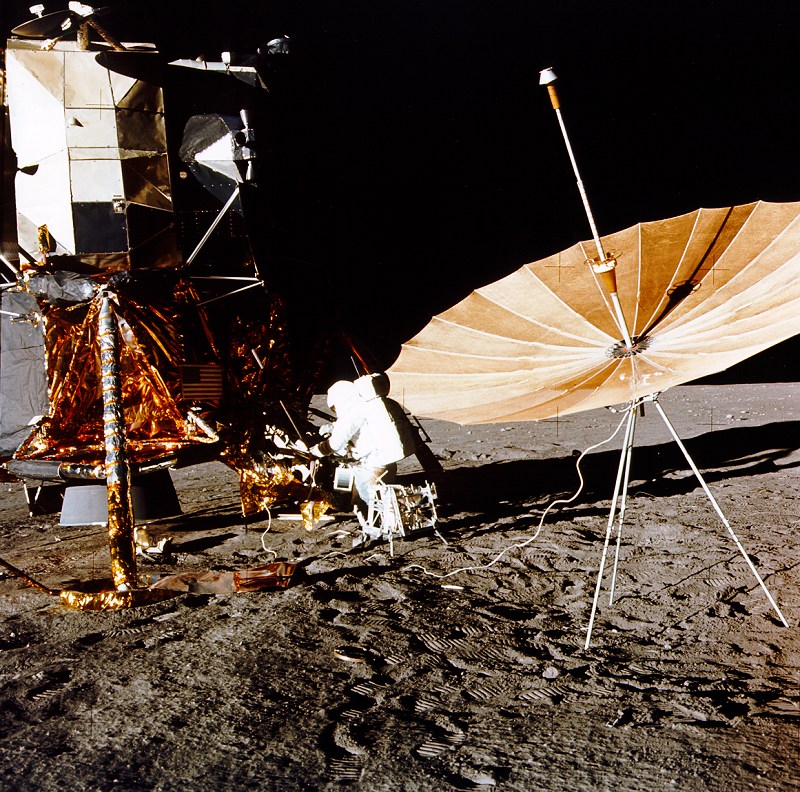
Apollo Erectable S Band Antenna |
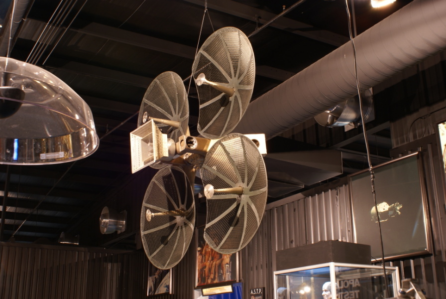
Apollo CSM Antenna in Museum |
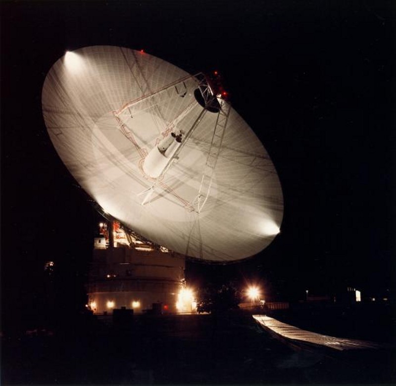
Goldstone Deep Space Network Antenna |
|
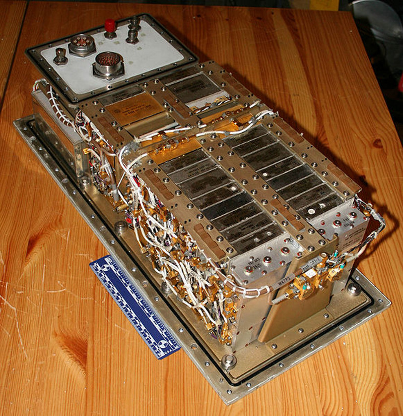
Apollo Unified S Band Transponder |
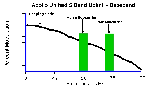
Apollo Unified S Band Uplink Spectrum |
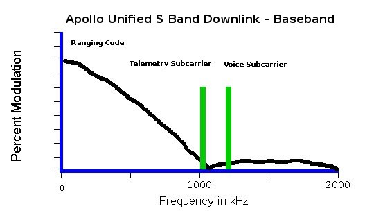
Apollo Unified S Band Downlink Spectrum |
Signal Characteristics
The Apollo Unified S-Band System used the 2025-2110 MHz band for uplinks (earth to space transmissions) and the 2200-2290 MHz band for downlinks (space to earth transmissions). The S-IVB upper stage had its own transponder so it could be tracked independently after separation from the Command Service Module until the stage passed or struck the moon. This tracking data greatly aided the analysis of impact shocks as recorded by seismometers installed in the surface by Apollo crews. The S-IVB shared its S-band frequency pair with the Lunar Module. This created no problem in a normal mission as the Lunar Module remained dormant until lunar orbit, by which time the S-IVB had already struck or passed the moon. However, it caused some interference during the Apollo 13 mission when the Lunar Module had to be used as a lifeboat well before Aquarius and the S-IVB reached the moon. The Lunar Module frequency pair was also used by the subsatellites left in lunar orbit by the later J-missions. They were deployed by the Command Service Module shortly before leaving lunar orbit returning to Earth, and the Lunar Module was no longer in use.
Apollo S-band Frequency Assignments:

Spacecraft 			Uplink (MHz)		Downlink (MHz)
--------------------------------------------------------------------------------------------
Command Module PM		2106.40625 		2287.5
Command Module FM					2272.5
Lunar Module 	(FM or PM)	2101.802083 		2282.5
S-IVB PM			2101.802083 		2282.5
S-IVB FM						2277.5
Lunar Rover			2101.802083 		2265.5
Apollo 11 Early ALSEP 		2119 			2276.5
Apollo 12 ALSEP 		2119 			2278.5
Apollo 14 ALSEP 		2119 			2279.5
Apollo 15 ALSEP			2119 			2278.0
Apollo 15 subsatellite		2101.802083		2282.5
Apollo 16 ALSEP 		2119 			2276.0
Apollo 17 ALSEP 		2119 			2275.5
Unified S Band System Normal Operating Modes
The S-band uplinks and downlinks normally used phase modulation (PM) containing data and voice subcarriers. Phase modulation, like frequency modulation, has a constant amplitude regardless of the voice or data it carries. This permits the use of energy efficient class C RF amplifiers. The modulation index is small, on the order of 1 radian, so the modulated signal occupied a bandwitdth slightly larger than a double sideband AM signal. The sidebands of an AM signal, however, would have been in phase and spectrally resembled mirror images of the actual modulating signal. Phase modulation sidebands are very different. The upper and lower sidebands are 90 degrees out of phase and theoretically extend out to infinity, and do not spectrally resemble the modulating signal. Most power, when the modulation index is small, is near the carrier frequency. For link analysis purposes, therefore, the pase modulation link can be analyzed as a narrow band signal.
On the uplink, there were narrow band subcarriers at 30 kHz and 70 kHz. The 30 kHz subcarrier was FM, 15 kHz bandwidth, and carried voice communications, while the 70 kHz carrier was phase-shift-keyed (PSK), 10 kHz bandwidth, with command data for the onboard computers. This latter capability, which could be blocked by the astronauts, was used primarily to update the onboard navigation and propulsion data with accurate state vectors determined by ground tracking. Uplinked command data was also used to execute maneuvers in an unmanned spacecraft, such as deorbiting the lunar module after it had been jettisoned in lunar orbit.
The Apollo downlink had a voice subcarrier at 1.25 MHz and telemetry data at 1.024 MHz. Telemetry could be at one of two rates, 1.6 kilobits/sec (low rate, 1/640 of the subcarrier frequency) and 51.2 kilobits/sec (high rate, 1/20 of the subcarrier frequency). High rate was used unless low rate was forced by poor link conditions, e.g., the use of a small earth receiving antenna, an omni spacecraft antenna, or the need to conserve spacecraft power by turning off its RF power amplifier. There was no voice subcarrier on the S-IVB.
Unified S Band System Backup and Emergency Modes
A backup voice mode was available that removed the 1.25 MHz voice subcarrier and transmitted voice as phase modulation on S-band carrier. This provided a few more dB of margin when the link was unusually degraded but worse voice quality than the normal voice mode. The two modes can be easily distinguished by how they react to signal fades. In the normal subcarrier voice mode the audio signal to noise ratio is usually very high. As the link degrades more noise appears suddenly and builds up rapidly until it completely obscures the astronauts' voices. An excellent example occurred during the Apollo 11 lunar landing when the lunar module structure occasionally obstructed the antenna's view of earth. The backup voice mode loses most of the advantages of FM and PM over AM signals; there is a constant background noise and the astronauts' voices vary with signal strength. This mode was used extensively during the Apollo 13 emergency to conserve battery power in the LM Aquarius and during Apollo 16 because of the failure of the steerable S-band antenna on the lunar module Orion. Much of the degredation, of the backup voice mode, noted on the Apollo audio recordings can be attributed to the receiving equipment. Additional "limiting" of the signal in the receiver would have reduced or eliminated the noise, but was not cost effective in the days before modern solid state high performance FM and PM detectors were created.
The Apollo Unified S Band System downlink also provided an "emergency key" capability consisting of a manually keyed continuous wave (CW) subcarrier at 512 kHz. The crew could then tap out their messages in Morse code if the downlink were too severely degraded to support even the backup voice mode. Although this mode had been tested (on Apollo 7) and most of the astronauts were trained in its use, this mode was never actually needed during any Apollo mission. There was no need for an uplink emergency key, due to the ground stations' excess power available. A typical Apollo S-band spacecraft exciter produced 300 mw, the downlink power amplifier 20 watts, while a typical uplink transmitter produced 10,000 watts, a power ratio of 26.9 dB. All of this doesn't count antenna gain. Rarely was the link budget capacity fully used during the Apollo program
Unified S Band System Ranging Measurements
Allocating uplink/downlink frequency pairs in a fixed ratio of 221/240 permitted the use of coherent transponders on the spacecraft. Coherent in this sense means there is a specific temporal relationship between the radio uplink and downlink signal phases. Then the phase or timing differences can be more easily analyzed to determine speed and distance between the spacecraft and tracking station. The Apollo spacecraft receives the uplink carrier, and with a phase locked loop system, generates a downlink carrier related in frequency by the ratio 240/221. When no uplink was received, the transponder downlink carrier was generated from a local oscillator at the nominal frequency. Uplink signals were derived from extremely precise time and frequency standards, and received downlinks were analysed in phase and frequency based on these same standards. A precise "two way" doppler shift was measured, and the resulting speed between the tracking station and spacecraft could be determined to within a few centimeters per second.
The Apollo Unified S Band System also provided distance measurements accurate to within 30 meters. The tracking station generated a pseudo-random-noise sequence at 994 kilobit/s and phase modulated it on the uplink carrier. The spacecraft transponder echoed this pseudo-noise signal back to earth on the downlink. The downlinked pseudo-noise was sent through a correlation process, meaning it was time-shifted to match the transmitted code, revealing the precise round trip light time to the spacecraft and back. This pseudo-random sequence repeated after about 5 seconds, enough to measure distance out to 540,000 miles. These ranging measurements consumed an appreciable fraction of the downlink capacity and were only needed for short periods, typically during handover from one ground station to the next. After the new uplink station achieved a 2-way coherent transponder lock with the spacecraft, the ranging signal was turned off and the range measurement was continually updated by doppler velocity measurements.
An S-band Transponder Experiment was performed on Apollo 14, 15, 16, and 17. In this experiment, the downlink frequency was accurately measured by the tracking station and compared with the frequency measured by a frequency counter on the spacecraft. Extremely small and irregular changes in the spacecraft's velocity were measured, enabling scientists to map concentrations in lunar mass. These "mascons" were evidence that the moon is not a homogenous sphere, but a jumbled mass of material of different densities. Mascons cause gradual changes in the orbits of lunar satellites and must be considered in planning navigation around the moon. Among the features studied in the S-band Transponder Experiment were impact basins Crisium, Imbrium, Nectaris, and Serenitatis, and impact craters Copernicus, Ptolemaeus, and Theophilus, the Apennine Mountains, and the Marius Hills.
Regarding azimuth and elevation measurements from each ground station, a sophisticated method was used which was more precise than merely "peaking the signal strength." Smaller antennas were used for acquiring the downlink and sensing "x and y axis phase differences" across the main antenna. Phase differences occur when the antenna isn't aimed exactly at the spacecraft; incoming wavefronts don't reach all parts of the parabolic reflector at the same time. When the phase errors are nulled, the antenna is boresighted on the spacecraft. As long as the antenna receives proper maintenance and is accurately aligned, aiming data can be used as part of the tracking solution.
Tracking data regarding radial distance, speed, elevation, and azimuth from the ground station was fed to an orbit determination program, which estimated the spacecraft state vector or orbital element set. Data from multiple tracking stations over time permitted precise refinements in the tracking data. This data was used to determine paramaters for the next rocket burn. After the burn, more tracking data was collected to evaluate the trajectory change and calculate a new state vector.
Unified S Band System FM and Video Signals
The normal operating mode of an Apollo S-band downlink transmitter was PM. This mode provided for coherent Doppler tracking, uplink commands, downlink telemetry and two-way voice, but not television. Video signals, even that from the slow scan camera used during the Apollo 11 EVA, are much wider in bandwidth than the other Apollo downlink signals. The PM link margin simply could not provide an acceptable picture, even when the largest available dishes were used. A means was also needed to transmit wideband engineering and scientific data, such as that recorded on a tape recorder and played back at high speed.
The answer to both needs was wideband frequency modulation (WBFM). FM with a large modulation index exhibits a strong capture or threshold effect. The output signal-to-noise ratio (SNR) can be significantly greater than the RF channel SNR provided that the RF SNR remains above a threshold, typically around 8-10 dB. In other words, for a slight increase in signal strength there is a large decrease in background noise. At some point, the background noise is essentially zero, and the video and subcarriers are loud and clear. This enhancement comes at a price: below the FM threshold, the output SNR is worse than the RF channel SNR. Reception is "all or nothing"; a receiving antenna too small to capture the video cannot capture the subcarriers either.
Potential difficulty receiving WBFM downlinks from Apollo spacecraft were enough of an issue for NASA that engineers created an Erectable S-Band Antenna. The Erectable S-Band Antenna was first flown on Apollo 11 and was intended to provide a stronger television signal for the first lunar moon walk. Because time during the brief Apollo 11 EVA was so precious, the expected 19-minute deployment of the antenna would have a major impact of productivity. Consequently, an assessment was made of the first few minutes of the black and white TV signal coming through the Lunar Module's steerable antenna. The signal was deemed adequate, so the Erectable S-Band wasn't used. It was used on both Apollo 12 and 14. Erectable S-Band Antenna deployment was intended to be easy enough that one person could do it in about 15 minutes. However, training convinced the Apollo 12 crew that they might have to work together when aiming the antenna at Earth. On both the Apollo 12 and 14 deployments, the astronauts worked as a team doing rough alignments and then, with one of them watching the sighting glass and making small adjustment to elevation using the flexible-cable crank, the other astronaut held the antenna to keep it relatively steady and prevent a collapse.
The Command Service Module carried separate FM and PM transmitters that could operate simultaneously, so voice and telemetry continued to be transmitted by PM while the video came down by FM. The Lunar Module only carried a single transmitter that could operate in either FM or PM, but not both. FM cannot be used for Doppler tracking, so the unar Module always transmitted PM during flight, reserving FM for when video was required during moonwalks and surface roving.
Non - Unified S Band System Signals
Project Apollo also carried several radars that operated independently of the Unified S Band System on their own frequencies, including the landing and rendezvous radars on the Lunar Module and a C-band radar transponder on the Command Service Module. VHF was used for short range voice and low rate telemetry between astronauts and the Lunar Module and Rover during EVAs; between the Lunar Module and Command Service Module; and between the Command Service Module and earth stations during the orbital and recovery phases of the mission. The Command Service Module had a backup capability to range the Lunar Module over its VHF voice links.
Interception of Apollo Spacecraft Signals
It is historically understood that the Soviet Union received telemetry signals from Apollo spacecraft, but there is no testimony or hard evidence of the interception. Soviet space infrastructure used different frequencies than the Apollo Manned Space Flight Network, and it is not clear that any large scale efforts were undertaken to build or modify equipment just to capture Apollo spacecraft data.
In the United States, the Federal Communications Commission recognized that amateur radio operators could receive Apollo spacecraft signals, but required any disclosure of information to comply with the "Communications Act of 1934." Specifically, NASA had to consent to the disclosure, since the raw downlinks were internal NASA communications and not broadcasts. Paul Wilson and Richard T. Knadle Jr. received voice transmissions from the Command Service Module of Apollo 15 in lunar orbit on the morning of August 1, 1971. In an article for QST magazine they provide a detailed description of their work, with photographs. At least two different radio amateurs, W4HHK and K2RIW, reported reception of Apollo 16 signals with home-built equipment. Larry Baysinger was successful in receiving the backpack AM transmitter carried by the Apollo 11 astronaut Neil Armstrong on VHF channel B (259.7 MHZ). Baysinger used a very large corner reflector antenna in his yard to receive weak but readable signals carrying both of the astronauts' voices.
There are other accounts of actual reception of voice via the Apollo Unified S Band System. Sven Grahn, Dick Flagg, and Wes Greenman used a 9 meter radio astronomy dish of the University of Florida to receive signals from Apollo 17. The 20 meter parabolic antenna at West Germany's Bochum Observatory was used to receive signals from Apollo missions 8 through 16.
Apollo 11 VHF Moon Walk Frequencies

Frequency		Mode 		Link Description
----------------------------------------------------------------------------------------------------
296.8 MHz (channel A) 	AM		Lunar Module to both Commander (Armstrong) and Lunar Module
					Pilot (Aldrin) relaying Capcom.

259.7 MHz (channel B) 	AM 		Commander (Armstrong) to Lunar Module carrying both
					Commander (Armstrong) and Lunar Module Pilot (Aldrin)

279.0 MHz (channel C)	AM		Lunar Module Pilot (Aldrin) to Commander (Armstrong)

Armstrong's VHF-B signal was then sent on S Band from the Lunar Module to tracking stations on Earth.
Further Reading on Apollo Spacecraft Communications
Here are some NASA documents and magazine articles with in depth data regarding the Apollo Unified S Band System:
|
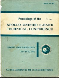
Apollo Unified S Band Conference Proceedings |
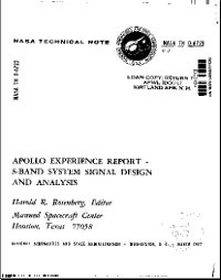
Apollo Unified S Band Experience Report |
|
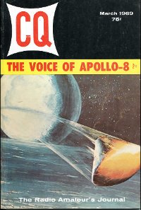
Radio Magazine Article of 03/1969 |
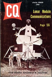
Radio Magazine Article of 06/1969 |
See the Video Series about Apollo S Band Communications
In late 2021 and early 2022, a YouTube channell, Curious Marc, produced an epic series of at least 13 parts about "Apollo Communications." We know here that the term refers to the Apollo Unified S Band Communications system. Curious Marc has already done in depth, hands on videos on tha Apollo Guidance Computer and other hardware. These involve not only discussion of the history, principles, of operation, and a close up look at the hardware. Curious Marc and his friends actually power up the hardware and operate it!
As to the Apollo communications and ranging equipment, Curious Marc does not disappoint. With the help of a couple of experts, and some amazing SDR programming, you can watch a powered up S band radio actually reansmit and receive live signals in the lab. If you are interested in Apollo history, or more generally in aerospace comms, do not miss this series. Episode 13 may not be the last, as there are more aspects of the system to explore, if they can continue to have access to these rare and historic items.
Here is a list of Curious Marc videos related to the Apollo communications and navigation systems. That's the S band comms and Apollo Guidance Computer plus DSKY control unit:
Apollo Guidance Computer Restoration Series

Apollo Guidance Computer, Part 1: The Restoration Project
Apollo Guidance Computer, Part 2: Power Supply
Apollo Guidance Computer, Part 3: Main Bus Undervolt
Apollo Guidance Computer, Part 4: We are Go for Power Up
Apollo Guidance Computer, Part 4 1/2: Bonus Clips
Apollo Guidance Computer, Part 5: Running Original Apollo Code
Apollo Guidance Computer, Part 6: Restoration Update
Apollo Guidance Computer, Part 7: Memory Module B12
Apollo Guidance Computer, Part 8: A Blinkenlight AGC
Apollo Guidance Computer, Part 9: Unboxing the Apollo IRIG Gyro
Apollo Guidance Computer, Part 10: Mike Flies Apollo 11's P63, Lunar Landing, on his AGC Replica
Apollo Guidance Computer, Part 11: Samtec Manufactures Nasa-spec Contacts for our AGC
Apollo Guidance Computer, Part 12: Return of the AGC
Apollo Guidance Computer, Part 13: The AGC Passes Self-Test with Emulated Memory
Apollo Guidance Computer, Part 14: Bringing up Fixed Rope Memory
Apollo Guidance Computer, Part 15: Recovering Lost Apollo Software at the Computer History Museum
Apollo Guidance Computer, Part 16: Digging into Potted Memory Module B11
Apollo Guidance Computer, Part 17: Carl's DSKY Hook up; Ken Mines a Bitcoin on the AGC
Apollo Guidance Computer, Part 18: Module B11 Rescue, Apollo 13 Style
Apollo Guidance Computer, Part 19: Th AGC Finally Works!
Apollo Guidance Computer, Part 20: An Electoluminescent DSKY Panel; Making an Accelerometer
Apollo Guidance Computer, Part 21: Playing Moon Landing on our Restored AGC
Apollo Guidance Computer, Part 22: Module B11 Fails Again!
Apollo Guidance Computer, Part 23: Flying Apollo 11 Moon Landings with the AGC
Apollo Guidance Computer, Part 24: Restored AGC computes Moon Landings in front of Its Creators
Apollo Guidance Computer, Part 25: Dan Lickly and Charles Simonyi REflect on the AGC
Apollo Guidance Computer, Part 26: We Open and Identify an AGC for Sale at an Upcoming Auction
Apollo Guidance Computer, Part 27: Recovering the Lost Apollo 10 LM Software
Apollo DSKY Panel Relight: the Whole Story
Apollo 10 Source Code: The Art of Commenting
Apollo 12 Source Code: Looking the original flown code printout and the 1202 error fix


Apollo Unified S Band Communications System

Apollo Comms, Part 1: Opening the S Band Transponder and Amplifier
Apollo Comms, Part 2: Inside the Traveling Wave Tube Amplifier
Apollo Comms, Part 3: Inside the S Band Transponder
Apollo Comms, Part 4: Transponder Power Up
Apollo Comms, Part 5: Transponder first Power On
Apollo Comms, Part 6: We Have Lock!
Apollo Comms, Part 7: Phase Modulated Receiver
Apollo Comms, Part 8: Which Crystal?
Apollo Comms, Part 9: Mystery Up-Data Box
Apollo Comms, Part 10: Apollo SDR Reboot
Apollo Comms, Part 11: Missing Phase-Modulated Transmitter Found!
Apollo Comms, Part 12: Apollo Uplinking with Modern Keysight Instruments
Apollo Comms, Part 13: First Double-Locked Link with Original NASA Ground Equipment
Apollo Comms, Part 14: Sending Commands to the Apollo Spacecraft
Apollo Comms, Part 15: Combining Voice, Data, and Ranging
Apollo Comms, Part 16: Stanford Dish Apollo Past
Apollo Comms, Part 17: Opening the Pre-Modulation Processor
Apollo Comms, Part 18: Updata Link Analog Mystery Solved
Apollo Comms, Part 19: Pre-Modulation Processor Grand Explanation
Apollo Comms, Part 20: Pre-Modulation Processor Power Up
Apollo Comms, Part 21: TV from the Moon
Apollo Comms, Part 22: How NASA Upgraded the Moon TV to Color
Apollo Comms, Part 23: Making Connectors and a Control Panel
Apollo Comms, Part 24: The Interface Simulator
Apollo Comms, Part 25: Central Timing Equipment
Apollo Comms, Part 26: Full System Integration & First Exhibit
Apollo Comms, Part 27: Quindar Tones Microphone Hack
© 2005 - 2026 AB9IL.net, All Rights Reserved.
Written and curated by Philip Collier / AB9IL.
About Philip Collier / AB9IL, Commentaries and Op-Eds, Contact, Privacy Policy and Disclosures, XML Sitemap.