Many radio hobbyists monitor the VHF air band and are satisfied with the results using discone or vertical antennas. For local and moderate distances, such antennas will deliver signals well above the noise level. If one has an interest in distant or low altitude aircraft, basic air band antennas are not satisfactory. Weak signal air band reception requires a combination of optimized antennas, low loss feedlines, and mast-mounted filtered preamplification.
Preamplifiers should not be the first choice for air band signal enhancement, because the gain often comes at the sacrifice of bandwidth and dynamic range. At best, a well made filter and low noise preamplifier combination will raise external atmospheric noise over internal receiver noise and provide high gain over a 2 to 3 MHz bandwidth. Filtering should reject out of band signals which could cause intermodulation or desensitization. Strong signals in the passband may still cause desensitization or intermodulation problems in the receiver. At worst, a wideband preamplifier will increase overloading problems and also fail to improve the system noise figure. In short: unless the objective is one fairly narrow range of frequencies with weak signals, avoid the use of preamplifiers. If there is an increase in vehicle ignition noise, lightning crackles, and other kinds of external background noise audible when the antenna is connected to the receiver, the noise figure is good enough.
AN AIR BAND LOG PERIODIC ANTENNA
A better solution is to install a high gain antenna and use the best possible low loss feedline. Offering wide bandwidth and moderate gain, log periodic antennas are a great choice for general air band listening. In addition to high gain, log periodic antennas offer superior front to back ratio and side lobe rejection. Below is a diagram with basic instructions for building an air band log periodic antenna with 9.5 dBi gain. This antenna, fed with high quality coaxial cable, will provide excellent performance for an air band monitoring station. It offers very high gain and directivity from 118 MHz to 136 MHz and is suitable for the most demanding air band monitoring stations.
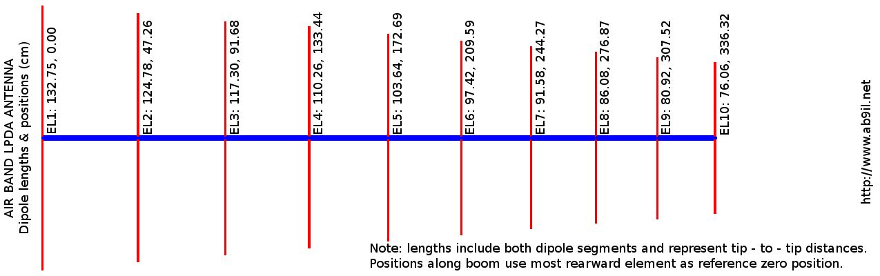
Note that the LPDA is essentially an array of dipoles, resonant at several frequencies across the design range and selected in such a manner that one dipole is "active" and the others serve as parasitic elements. Each dipole has a specific length shown in the diagram, which is in centimeters from tip to tip. Each element also has a position along the boom, measured as a distance in centimeters from the most rearward element. The most basic LPDA is a series of precisely cut copper or aluminum rods mounted to a wooden boom and fed in alternating phase (criscrossing feedline). Actual log periodic antennas for the VHF air band tend to not use criscrossing feedlines, opting instead to use two parallel booms with alternating dipole elements attached. Electrically, the dipoles are being fed in opposite phases from open wire feedline.
AIR BAND LOG PERIODIC ANTENNA DESIGN DATA

Number of elements (n): 10
Axial Length: 336.32420635098277 cm
tao = 0.94,  sigma = 0.178  gain = 9.5 dBi

ELEMENT	LENGTH		BOOM POSITION (CM)
-----------------------------------------------------------------------------
01			132.747457		000.0000000
02			124.782610		047.2580959
03			117.295653		091.6807058
04			110.257913		133.4379591
05			103.642438		172.6897771
06			097.423892		209.5864859
07			091.578458		244.2693921
08			086.083750		276.8713239
09			080.918725		307.5171396
10			076.063601		336.3242064
Have a look at this example of a very solidly built antenna built by L. B. Cebik, W4RNL, for the 2 meter amateur radio band. Much of the construction technique seen in the article can be applied to construction of the 10 element air band LPDA antenna. See that a sound construction method is to build two identical metal booms, with alternating left and right (or upper and lower) elements attached to accomplish the proper 180 degree phasing. When the booms are mounted in parallel and with about 1.5 centimeters separation, the antenna appears as a perfect set of phased dipoles and presents a good impedance match for quality feedline. The W4RNL 2 meter antenna uses threaded elements in a "U channel" boom, but that is not entirely necessary. Good srtuctural integrity is possible if the elements are not threaded, but soldered to the boom on both sides of the channel. Do not weld! Welding greatly reduces the strength of the metal, and the antenna will not withstand strong winds or bird perchings.
|
High gain air band |
It is practical to make two identical booms |
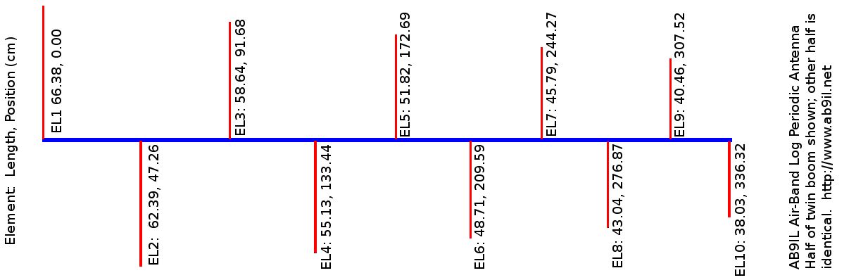
To build the 10 element log periodic air band antenna, construct two identical booms with element positions and lengths as given in the above diagram. The booms can be copper pipe or aluminum "U" channel; dipole elements should be made of the same metal as the boom to prevent corrosion over time due to electrolysis. The two booms should be separated with 1/2" or 1.5 cm non conductive material at each end.
Note that careful measuring, drilling, and cutting of all parts is essential for good performance of the antenna. Whether "U" channel or copper pipe is used for the boom, be sure to cut each half-element so that the distance from tip to centerline of the boom is exactly 1/2 of the tip-to-tip distance. In other words, account for the length of element secured within the boom, and ensure that the dipoles are not asymmetrical or shorter than the design specifications. Measure, mark, cut or drill, secure, and measure again!
Feeding the log periodic antenna is simple. Attach the coaxial cable center conductor to one boom near the feed point of the shortest dipole, and the shield to the corresponding point on the other boom. Avoid letting the cable hang from the antenna. It should be secured to the booms with plastic cable ties and routed to the antenna mast, then guided to the receiver location. Weatherproof with hot melt glue, spray lacquer, or self-amalgamating tape.
Aircraft radio signals are vertically polarized, so it is suggested to mount the air band LPDA with its elements vertically oriented. Use non-conductive material to attach the antenna to its mast; do not allow anything to short the booms.
AN AIR BAND YAGI ANTENNA
Another option for weak or distant aircraft is construction of a high gain yagi antenna, and feeding it directly with low loss coaxial cable. Though having a narrower bandwidth than log periodic air band antennas, yagis are easier to construct and provide high gain near the design frequency. A 10 element air band yagi antenna designed for 128 MHz is shown here, and it performs well for reception even at 118 MHz and 137 MHz. It is a stunning performer at its design frequency! One user on the east coast of the USA reports fantastic long range ACARS reception of oceanic flights.
This 10 element air band yagi is based on the K1FO design, scaled to the center of the air band voice range. Theoretical gain is about 13 dBi. A wooden or fiberglass boom is used, and the elements are 1/8" or 3.26 mm solid copper. Number 8 solid copper ground wire is an easy to find source for element material. Impedance matching is accomplished by using a "J Pole" driven element fed by coaxial cable. To some, the antenna will look familiar. It was adapted from the "Cheap Yagi" concept of Kent Britain, WA5VJB.
AIR BAND YAGI ANTENNA DATA

Design Frequency: 128 MHz
Number of elements: 10
Axial Length: 431.29 cm
gain = 13 dBi

ELEMENT	LENGTH	BOOM POSITION (CM)
-----------------------------------------------------------------------
01			116.86		000.00
02			107.51		035.12
03			107.62		050.32
04			104.92		078.69
05			103.12		118.21
06			102.00		166.84
07			100.98 		223.58
08			100.31		287.41
09			099.86		356.65
10			099.41		431.29
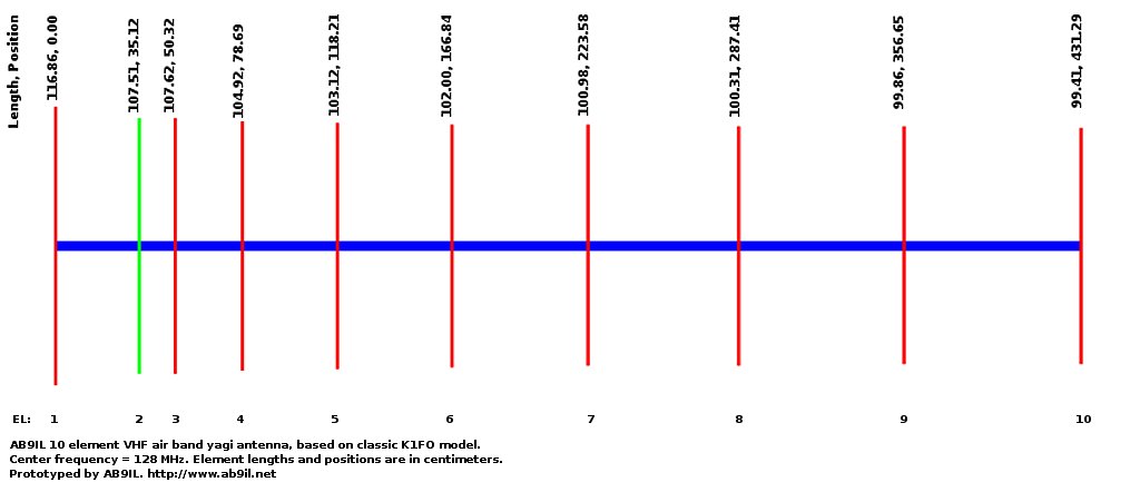
High gain air band yagi antenna diagram.
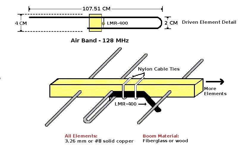
High gain air band yagi antenna construction details.
To construct this antenna, print the diagrams given above. Obtain a suitable length of fiberglass or wooden boom material, plus enough copper rod or solid wire for the elements. Mark and carefully drill holes in the boom. Then cut the proper lengths of copper for the elements and mount them in the boom. Form a "J pole" for the driven element and mount it in the boom. Double check all elements for proper length and centering on the boom, then secure them in place with epoxy.
The coaxial feedline is attached as follows: center conductor to the hook of the "J" pole and shield to the opposite side of the "J" as shown in above. Use cable ties to secure the coaxial cable to the boom. Weatherproof with hot melt glue, spray lacquer, or self-amalgamating tape.
Either of the above antennas will enhance one's ability to monitor air band activity. ATC ground to air transmissions are often difficult to hear at long distances. Low altitude aircraft are similarly difficult to receive, and require high gain directional antennas for suitable reception. With these antennas (on a rooftop or 30 foot mast), one should expect clear reception of aircraft down to 5000 feet at 200 miles and ATC stations at a range of about 40 miles over flat terrain. Very long range reception is possible if either of these high gain air band antennas are mounted on a skyscraper rooftop or other high terrain.
© 2005 - 2026 AB9IL.net, All Rights Reserved.
Written and curated by Philip Collier / AB9IL.
About Philip Collier / AB9IL, Commentaries and Op-Eds, Contact, Privacy Policy and Disclosures, XML Sitemap.